MEGR 3090: Design Webpage
By: Joseph Petite
LESSONS LEARNED
-
The main thing I learned throughout this project was how to convert my previous knowledge of other coding languages to Python.
-
The second thing I learned through this assignment was that servo motors will jitter uncontrollably unless you utilize PiGPIO.
-
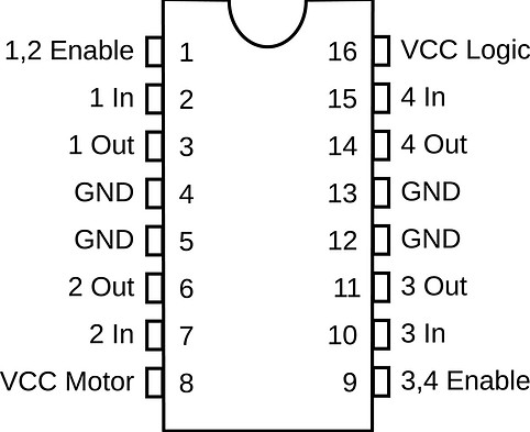
Another thing I learned through this project was how to wire and code a DC motor through the utilization of L298D motor driver.
-
Yet another thing I continue to relearn is that == is NOT the same as =.
-
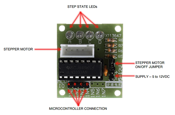
The last thing I learned throughout this process was how to wire and use a ULN2003 driver board.
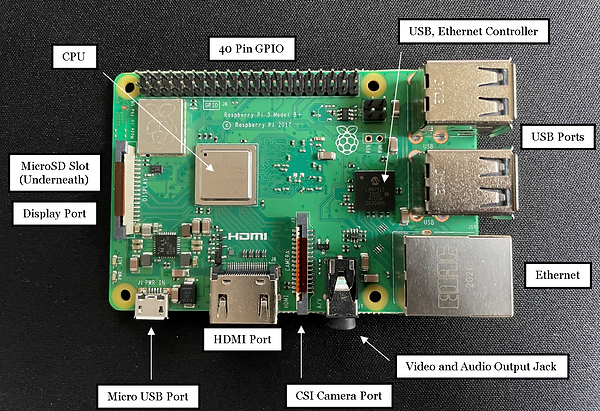
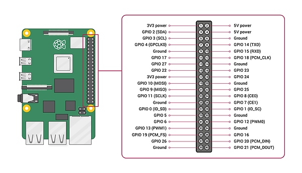
RASPBERRY PI, L298D and ULN2003 BREAKDOWN

ASSIGNMENT PART 1
(Make an LED do something else than what was showcased in the reading)
For this part of the project I decided to alter the blink code observed in the reading and carried out during class so that it would progressively get quicker until eventually looping back around.
SCHEMATIC
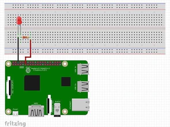
CIRCUIT

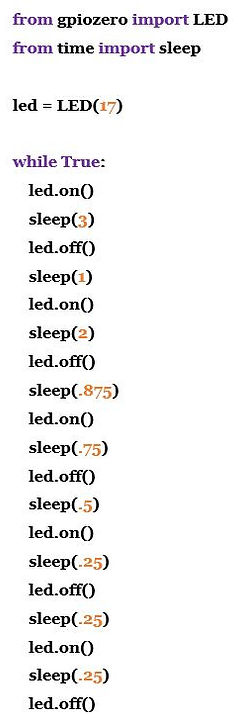
CODE

-
First and foremost, the LED is connected to GPIO 17 of the Raspberry Pi and is therefore represented as such within the code.
-
This code operates instantaneously once it is run with no additional inputs. Due to this a "While True" loop is utilized for this task.
-
The first action of this code is to turn on the led. The led is then kept on for a set period of time. In this case, that set period of time is three seconds.
-
This is achieved through the use of the "sleep" command which pauses the codes progression until the define time is concluded.
-
Once the set sleep time is completed the code then continues onto the next command, turning off the LED for one second. This is achieved by once again utilizing the "sleep" command.
-
This process is then repeated many times, slowly reducing the time in which the code sleeps.
-
As a result of this the blinking of the LED becomes more and more rapid until the code loops back around and starts again.
VIDEO
ASSIGNMENT PART 2
(Make a button do something else than what was showcased in the reading)
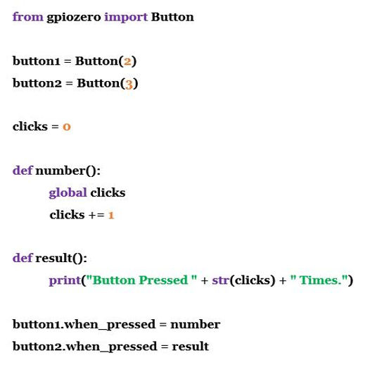
For this part of the project I created a counting system in which the python code keeps track of how many times a button is pushed. This code then informs you of how many times the button has been pushed by pressing a second button.
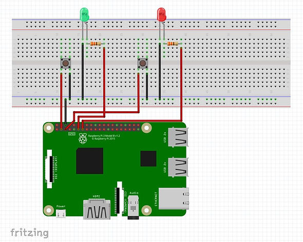
SCHEMATIC
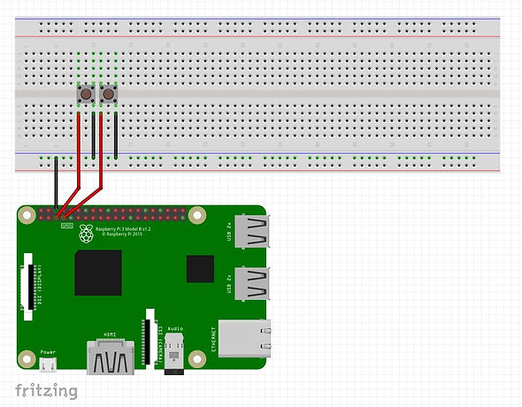
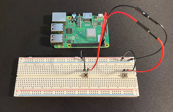
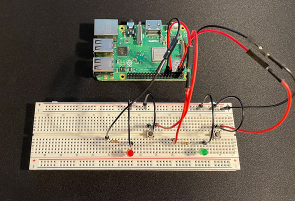
CIRCUIT
CODE
-
First and foremost, button number one, seen on the right hand side of the image above, is connected to GPIO 2 of the Raspberry Pi and is therefore defined as such within the code.
-
Button number two, seen on the left hand side of the image above, is connected to GPIO 3 of the Raspberry Pi and is therefore defined as such within the code.
-
Button number one, seen on the right hand side of the image shown above, is monitored by the code for presses or "clicks".
-
Each time this button is pressed it is represented in the code as a "click".
-
These "clicks" represent a overall numerical value within the code and is therefore is preset to zero each time the code is run.
-
Every time this first button is pressed, the code is instructed to add 1 "click", to the global, or total value.
-
These parameters are used to define the function called "number" which then can be easily called each time the button is pressed.
-
The second button, seen on the left hand side of the image above, reports the number of times the first button had been pressed.
-
This is expressed through the "print" command which is defined in the function called "results".
VIDEO
ASSIGNMENT PART 3
(Make an LED and button do something else than what was showcased in the reading)
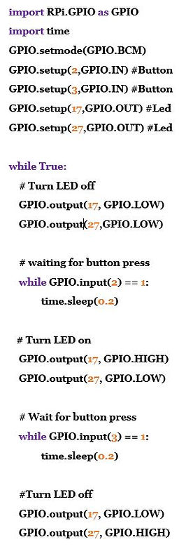
For this part of the project I created a system in which two LED's were controlled by two buttons. Once one button was pushed its correlating LED would turn on and stay on. After the second button is pushed its correlating LED will turn on and stay on however the other LED will be turned off.
SCHEMATIC
CIRCUIT
CODE
-
First and foremost, each of the two buttons and LED's are both defined as either an input or output and is paired with its correlating pin number.
-
Both buttons are defined as inputs as the code receives data from them in order to carry out the remainder of the code and the desired results
-
Button one, seen on the right hand side of the image above, is connected to GPIO 2 and is therefore defined as such within the code.
-
Button two, seen on the left hand side of the image above, is connected to GPIO 3 and is therefore defined as such within the code.
-
The LED's on the other hand are both defined as outputs within the code as their actions are controlled by the code and its data.
-
The green LED is connected to GPIO 17 and is therefore defined as such within the code.
-
The red LED is connected to GPIO 27 and is therefore defined as such within the code.
-
This code works the the use of 1's and 0's. When a button is pressed it is represented as a "1" within the code. This value is then utilized to control other aspects.
-
As seen to the left, the first part of this code presets both LED outputs to a low voltage, turning them off.
-
When button number one is pressed its state is updated to a "1". This value is then utilized to alter the green LED's state to a high voltage, turning it on, while keeping the red LED's state to a low voltage and therefore staying off.
-
On the other hand, When button number two is pressed its state is updated to a "1", overwriting the state of the first button. This value is then utilized to alter the red LED's state to a high voltage, turning it on, while changing the green LED's state to a low voltage, turning it off.
VIDEO
ASSIGNMENT PART 4
(Make a button do something else than what was showcased in the reading)
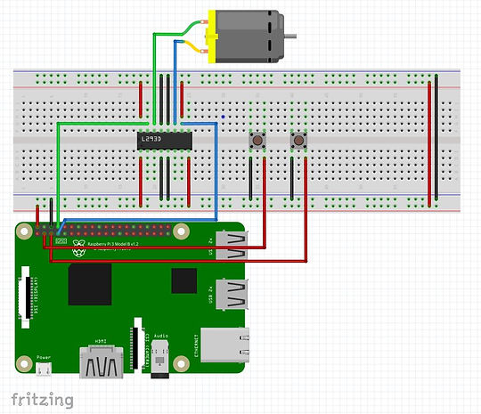
For this part of the assignment I created a system in which the direction of a DC motor's rotation was controlled by two buttons. Button one made the DC motor rotate in a forwards direction while button two made the DC motor rotate in the reverse direction.
SCHEMATIC
CIRCUIT

CODE

-
First and foremost, the pins utilized to connect the DC motor and the motor driver to the Raspberry Pi were defined as "robot".
-
The pins utilized for this part of the circuit included pins 4,14,17 and 18.
-
Once the DC motor and motor driver pins where declared, two buttons were separately defined as forwards ("fw") or backwards ("bw").
-
The button that controlled forward motion of the DC motor was paired with pin GPIO 2 while the button in control of backwards motion was paired with pin GPIO 3.
-
The rest of this code utilized the "when_pressed" command paired with the "when_released" command.
-
When either button is pressed down its defined action will occur.
-
For example when the "fw" button is pressed down the DC motor will rotate in a forwards direction.
-
Once this button is released however the code instructs the DC motor to stop all rotation.
VIDEO
ASSIGNMENT PART 5
(Make the servo motor do something when the button is pressed)
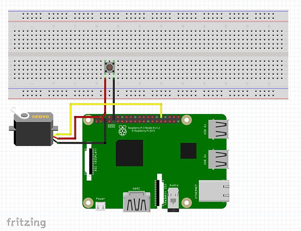
For this part of the project I created a code that would rotate the servo motor to predefined positions based on how many times a button had been pressed.
SCHEMATIC
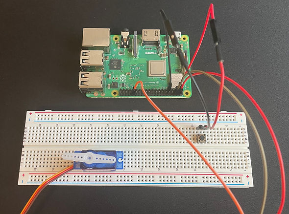
CIRCUIT
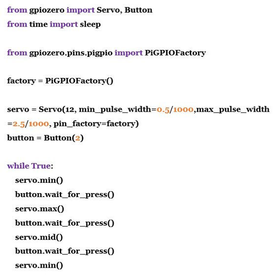
CODE
-
In order to reduce servo jitter, PiGPIO was utilized for this part of the project.
-
The servo motor was connected to GPIO 12 on the Raspberry Pi and therefore was represented as such within the code. In addition its pulse was altered so that a full 180 degrees of rotation was achievable.
-
The button was connected to GPIO 2 on the Raspberry Pi and therefore was represented as such within the code.
-
The entirety of this code and the servo motor's actions were achieved through the use of the "wait_for_press" command.
-
Once the code is run, the servo motor is automatically instructed to rotate to 0 degrees or its min position.
-
Once the button had been pressed once, the servo motor will be instructed to rotate to its max position or 180 degrees.
-
Pressing the button a second time will instruct the servo motor to rotate to its mid position or 90 degrees.
-
Pressing the button a third time will instruct the servo motor to rotate back to its min position or 0 degrees.
VIDEO
ASSIGNMENT PART 6
(Make a stepper motor do something when a button is pressed)
For this part of the assignment I made a system in which a stepper motor will rotate for half a full rotation once a button is pressed.
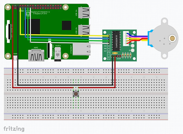
SCHEMATIC
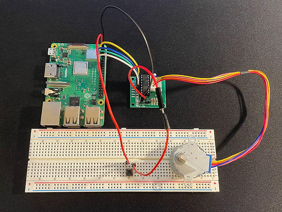
CIRCUIT
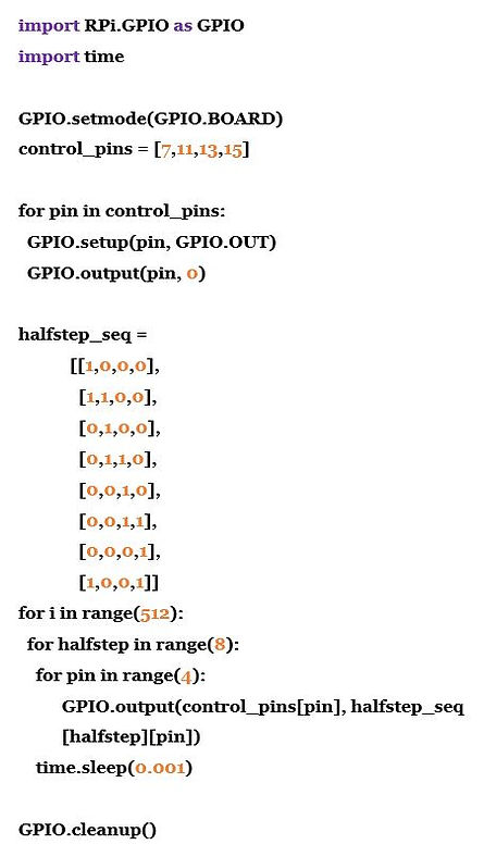
CODE
-
First and foremost, the stepper motors control pins, wired through the motor driver, were defined within the code.
-
The pins utilized to connect the motor driver to the Raspberry Pi and control the motor were 7,11,13 and 15.
-
After setting up the GPIO pins we then declared an activation sequence.
-
This sequence controls the order in which the stepper motor's windings are activated.
-
There are four windings in this particular stepper motor and each one is represented as either a 1 or 0 within our code.
-
If a winding is declared as a 1 it will be activated, rotating the magnet towards its direction.
-
These sequences are forms so that the windings are activated in a smooth circular direction, rotating the motor as such.
-
This particular sequence rotates the stepper motor for exactly half a full rotation.