MEGR 3090: Design Webpage
By: Joseph Petite
PROJECT PHASE 2
LESSONS LEARNED
-
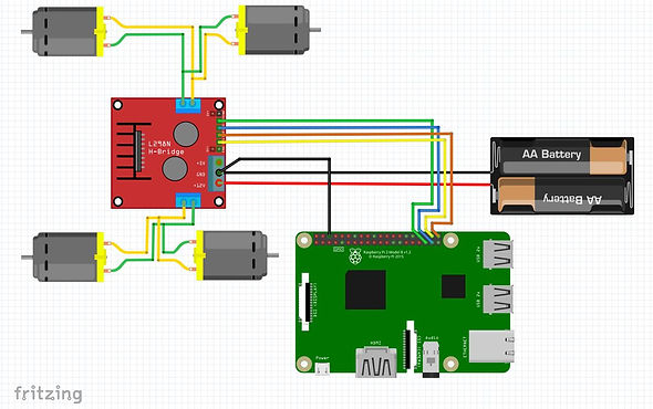
The first thing I learned through this assignment was that four DC motors could be meagered together and controlled by a single L298N motor driver.
-
The next thing I learn through this project is that these same four DC motors can be powered by a single battery pack and two 3.7V, 18650 batteries.
-
Another thing I learned was how to format a Python code that would allows users to control multiple DC motors and their directions through Blynk.
-
The next thing I learned was how to utilize a slider widget in blynk in order to control a servo motor and its change of angle.
-
Another thing that I learned was that ASA filament does not print as clean or accurate as PLA.
-
The next thing I learned was how to combine multiple separate files of python code in order to control multiple sensors with one file.
-
The last thing I learned was how to call and run multiple different python code files simultaneously from a single master script
3D MODELING
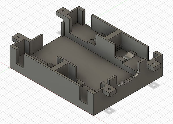
3D Model for the Base of the Chassis

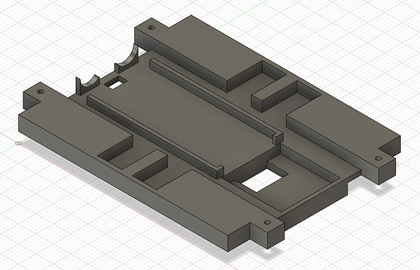
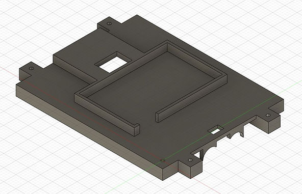
3D Model for the Top of the Chassis
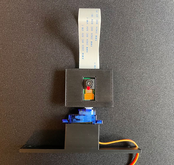
3D Model for Servo Motor and Camera Mount


3D Model for the Base of the Chassis w/ DC Motors and Ultrasonic Sensor
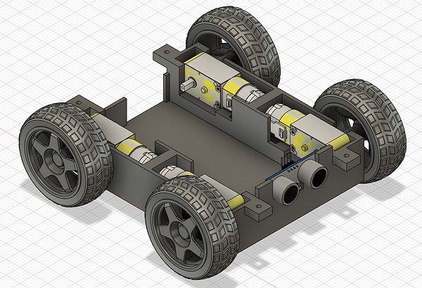

3D Model for the Base of the Chassis w/ All Components
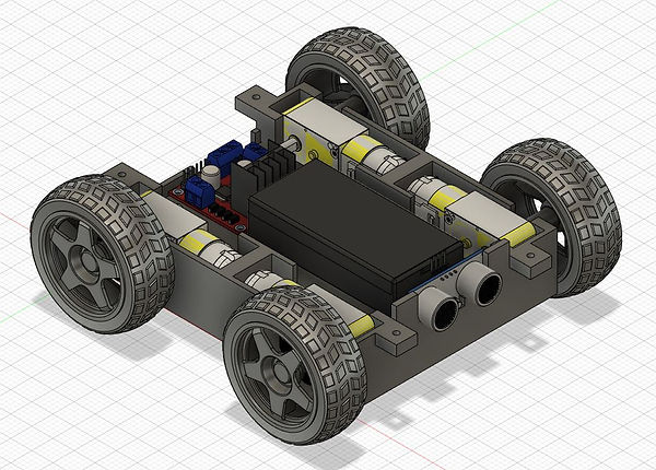

3D Model for Robot w/ All Components and Top


3D Model for Robot w/ All Components, Top and Camera System


DC MOTOR DIRECTIONAL TEST
At this point in the project I decided to utilize LimitOS in order to test which way the motors would spin when positioned in the desired orientation. Doing this allowed me to pair motors together that will spin in the same direction, effectively only having to code for "two" motor directions down the line.
Schematic
Physical Circuit

Test Video
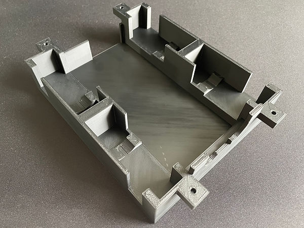
ROBOT 3D PRINTS
Physical 3D Print for the Chassis Base

Physical 3D Print for the Chassis Top
.jpg)
.jpg)
Physical 3D Print for the Servo Motor and Camera Mount

PHYSICAL ASSEMBLY


DC MOTOR CONTROL
(PYTHON+BLYNK)
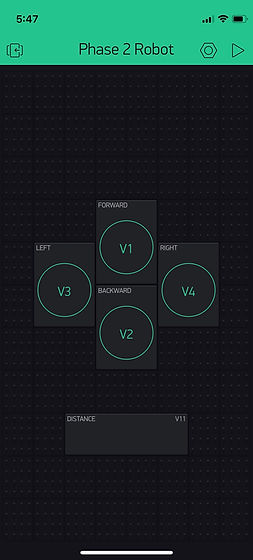
Blynk Setup

Schematic

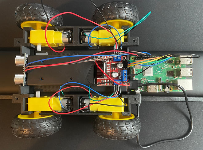
Physical Circuit

Python Code


Test Video
ULTRASONIC SENSOR CONTROL
(PYTHON+BLYNK)
Blynk Setup


Schematic

Physical Circuit

Python Code (Gathered from Dr. Fagan's Example Code)

Test Video
DC MOTOR AND ULTRASONIC SENSOR CONTROL
(PYTHON+BLYNK)
Blynk Setup
Schematic

Physical Circuit
.jpg)
Python Code


Test Video
CAMERA FEED AND HORIZONTAL SERVO PAN
(PYTHON+BLYNK)
Blynk Setup


Schematic

Physical Circuit

Python Code
The code shown below ("MasterCode") runs the two python scripts responsible for servo pan control as well as the Raspberry Pi's camera livestream simultaneously.

The code shown below ("ServoPan") controls the degree at which the servo, and therefor the camera, is rotated.

The code shown below ("Video") controls the camera and creates a livestream that can be then viewed from blynk. The issue with this strategy is the significant stream lag.


Test Video
PHASE 2: FINAL ROBOT
(PYTHON+BLYNK)
Blynk Setup

Schematic

Physical Circuit

Python Code
The code shown below ("Phase2MasterCode") runs the two python scripts responsible for full robot control as well as the Raspberry Pi's camera livestream simultaneously.

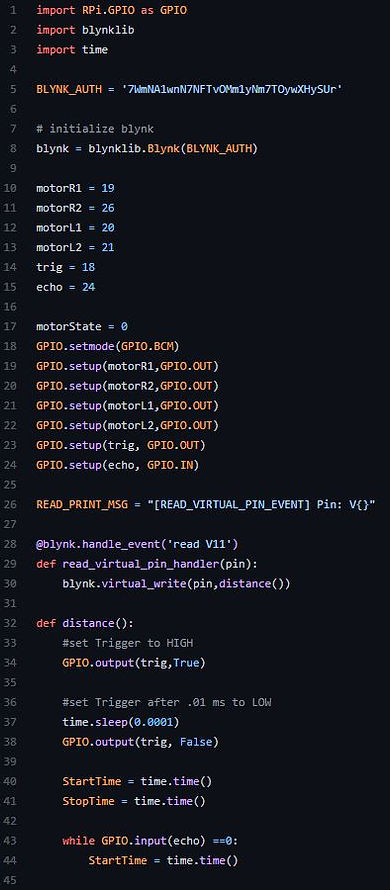
The code shown below ("Phase2Final") is responsible for full control over the robot. This includes control over the dc motors, distance monitoring with the ultrasonic sensor and finally camera panning with a servo motor


Final Product Video
SOURCES
1. https://projects.raspberrypi.org/en/projects/raspberry-pi-setting-up
3. https://www.blackmagicdesign.com/products/davinciresolve/
4. https://www.youtube.com/watch?v=hblqZLyWroE
5. https://tutorial.cytron.io/2021/03/16/blynk-video-streaming-using-raspberry-pi-camera/
6. Dr. Fagan's sample code for ultrasonic sensors and DC motors
7. https://pymotw.com/2/multiprocessing/basics.html
8. https://www.youtube.com/watch?v=EYrEjC3QEew